 |
Download a printer-friendly version of this document (PDF format)

Isolators
U-Spring

M/RAD is a manufacturer of certain "off the shelf" style isolators. Our specialty and area of expertise is with the DESIGN and FABRICATION of CUSTOM isolators and isolation systems.
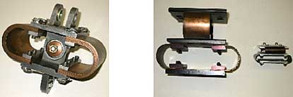
A novel concept in an all-metal vibration isolator for delicate navigation or electronic equipment has been developed by M/RAD. This mount assembly utilizes a unique configuration of U-shaped springs to obtain stiffness characteristics. System damping is provided by integral friction or viscous dampers, which are consistent over a wide temperature range. The suspension system provides freedom for translation, but maintains high stiffness constraint against rotation. As a result, precise static alignment of the mounted unit is possible and the error in angular returnability is virtually eliminated. The mount provides excellent shock attenuation, improved vibration isolation at high frequencies, low resonant peaks, decoupled angular and translational modes and angular alignment returnability of 30 seconds of arc.
This isolator can be designed to accommodate any payload from 1 lb to 5,000 lbs per isolator and provide any stiffness, hence, any resonant frequency. Price, of course, depends upon dimensions, quantity and complexity of requirements.
Concepts such as this are of typical nature for M/RAD. If you are interested in further assistance for vibration/shock control isolators, please contact us. We are always eager to serve.
M/RAD ACTIVE ISOLATOR (AIR SPRINGS)
 Isolators operate from a continuous supply of compressed air or other inert gas to provide isolation of mounted equipment from vibration and shock, and to provide continuous automatic leveling by means of pneumatic support elements control led by height sensing servo-valves. Isolators operate from a continuous supply of compressed air or other inert gas to provide isolation of mounted equipment from vibration and shock, and to provide continuous automatic leveling by means of pneumatic support elements control led by height sensing servo-valves.
Each isolator will contain aspring chamberand a damping chamber, orificed together to provide damping in the vertical axes.
Three (3) mechanical height sensing ser o-valves will control the height and internal pressure of the isolators Correction will be smooth and even. Each valve will control one set of isolators. Height adiustmant to be 3/6 inch.
A gauge panel, with all necessary gauges, pressure regulator,fitter and lubricator will be furnished.
The isolation system will require plant air at 60 psi minimum in 1/4 inch pipe within 5 feet of the installation. A shut off valve is recommended at the termination of the pipe.
NOTE: "Instrument Air" is not required provided plant air Supply iS clean and dry No other source of power is required.
Pedestals may be supplied with the M/RAD air springs to provide any convenient work surace height.
ISOLATION PERFORMANCE
Perormance of the isolation system will approximate the following throughout the load range.
| Vertical Natural Frequency: |
2 Hz
|
| Verical Damping: |
10%of critical
|
| Horizontal Natural Frequency: |
Approximately 1 Hz
|
| Horizontal Damping: |
10tK of critical
|
Attenuation Rate:
|
12 db per octave at frequencies above approxi mately three times system natural frequency
|
Static height of the isolators will be maintained within 0.001 inch for load changes of less 1han 2 percent and less than 0.005 inch for load changes up to 20 percent. When subjected to load changes the system shall automatioally relevel the supported mass in a time period of not more than 100 seconds
SPECIFICATIONS
The isolation system will include three (3) or more pneumatic isolators to support the isolated mass and anticipated equipment with an internal pressure of not more than 60 psig but with a capability to operate at 100 psig.
M/RAD
Part No.
|
Natunal
Frequency
(approx.)
Hz.
|
Single
Isolator Load
Capacity
@ 80 psig
lbs. |
System Load
Capacity
(3 Isolators)
@ 80 psig
lbs.
|
Isolator
Height
In.
|
Isolator
Diameter
In.
|
D1 1020 26-2
D 11020 20-2
D 11020 22-2
D 11020 21-2
D 11 020-26-2
D 11020-203 2
D 11 020-29-2
D1 1020-211-2
|
20
2.0
20
2.0
2.0
2.0
2.0
2.0
|
1,670
2,130
4,260
6,540
9,590 14,970
2O,060 32,550
|
5,010
6,390
12,640
19,620 26,770
44,910
60,180 97,650
|
10
10.5
11.5
11.5
11.5
11.5
11.5
13
|
6.6
10.2
12.9
151
17.4
20.0
22.4
27.9
|
|
|


